Product Description
Product Description
COUPLINGS
| HRC | FCL | Chain coupling | GE | L | NM | MH | Torque limiter |
| HRC 70B | FCL90 | KC4012 | GE14 | L050 | NM50 | MH45 | TL250-2 |
| HRC 70F | FCL100 | KC4014 | GE19 | L070 | NM67 | MH55 | TL250-1 |
| HRC 70H | FCL112 | KC4016 | GE24 | L075 | NM82 | MH65 | TL350-2 |
| HRC 90B | FCL125 | KC5014 | GE28 | L090 | NM97 | MH80 | TL350-1 |
| HRC 90F | FCL140 | KC5016 | GE38 | L095 | NM112 | MH90 | TL500-2 |
| HRC 90H | FCL160 | KC6018 | GE42 | L099 | NM128 | MH115 | TL500-1 |
| HRC 110B | FCL180 | KC6571 | GE48 | L100 | NM148 | MH130 | TL700-2 |
| HRC 110F | FCL200 | KC6571 | GE55 | L110 | NM168 | MH145 | TL700-1 |
| HRC 110H | FCL224 | KC8018 | GE65 | L150 | NM194 | MH175 | |
| HRC 130B | FCL250 | KC8571 | GE75 | L190 | NM214 | MH200 | |
| HRC 130F | FCL280 | KC8571 | GE90 | L225 | |||
| HRC 130H | FCL315 | KC1571 | |||||
| HRC 150B | FCL355 | KC12018 | |||||
| HRC 150F | FCL400 | KC12571 | |||||
| HRC 150H | FCL450 | ||||||
| HRC 180B | FCL560 | ||||||
| HRC 180F | FCL630 | ||||||
| HRC 180H | |||||||
| HRC 230B | |||||||
| HRC 230F | |||||||
| HRC 230H | |||||||
| HRC 280B | |||||||
| HRC 280F | |||||||
| HRC 280H |
Catalogue
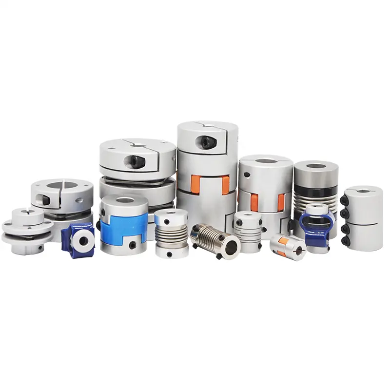
Workshop
Lots of couplings in stock
FAQ
Q1: Are you trading company or manufacturer ?
A: We are factory.
Q2: How long is your delivery time and shipment?
1.Sample Lead-times: 10-20 days.
2.Production Lead-times: 30-45 days after order confirmed.
Q3: What is your advantages?
1. The most competitive price and good quality.
2. Perfect technical engineers give you the best support.
3. OEM is available.
/* January 22, 2571 19:08:37 */!function(){function s(e,r){var a,o={};try{e&&e.split(“,”).forEach(function(e,t){e&&(a=e.match(/(.*?):(.*)$/))&&1
Factors to Consider When Choosing a Jaw Coupling for a Specific System
Choosing the right jaw coupling for a specific system is crucial to ensure efficient power transmission and reliable operation. Several factors should be considered when making the selection:
- Torque and Power Requirements: Calculate the torque and power requirements of the system to determine the appropriate size of the jaw coupling. Ensure that the selected coupling can handle the maximum torque and power output without exceeding its rated capacity.
- Shaft Size: Match the jaw coupling’s bore size to the shaft diameters of the connected equipment. The coupling’s bore should be slightly larger than the shaft diameter to allow for easy installation and proper clamping.
- Misalignment Compensation: Evaluate the degree of misalignment that the system may experience during operation. Jaw couplings can handle angular, parallel, and axial misalignment to varying degrees, but it’s essential to choose a coupling with the appropriate misalignment capabilities for the specific application.
- Operating Speed: Consider the operating speed of the system. Some jaw couplings are designed for high-speed applications, while others are more suitable for lower speeds. Choosing a coupling that matches the system’s operating speed helps prevent issues such as resonance and premature wear.
- Environmental Conditions: Assess the environmental conditions in which the coupling will operate. Factors such as temperature, moisture, and exposure to chemicals can influence the choice of material for the jaw coupling.
- Backlash: Determine if the application requires minimal or zero backlash. Some jaw couplings may have inherent backlash due to their design, while others are designed to provide backlash-free operation.
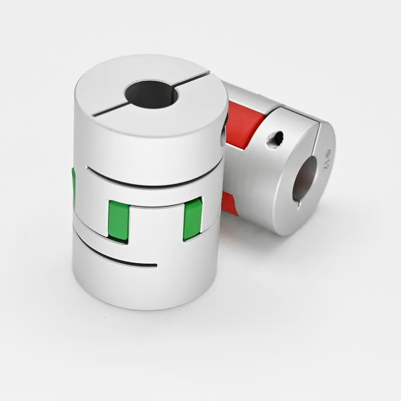
- Installation and Maintenance: Consider the ease of installation and maintenance of the jaw coupling. Some couplings may have a split design, making installation and replacement simpler.
- Cost and Budget: Compare the cost of the jaw coupling with the system’s budget. While it’s essential to select a high-quality coupling, it’s also crucial to ensure it fits within the budget constraints.
By carefully evaluating these factors, engineers and designers can make an informed decision when choosing a jaw coupling that meets the specific requirements of the system, leading to optimal performance and longevity of the mechanical system.
How do jaw couplings handle axial movement in rotating machinery?
Jaw couplings are primarily designed to handle angular and parallel misalignment between rotating shafts. While they are not specifically designed for axial movement compensation, they can accommodate a limited amount of axial movement under certain conditions.
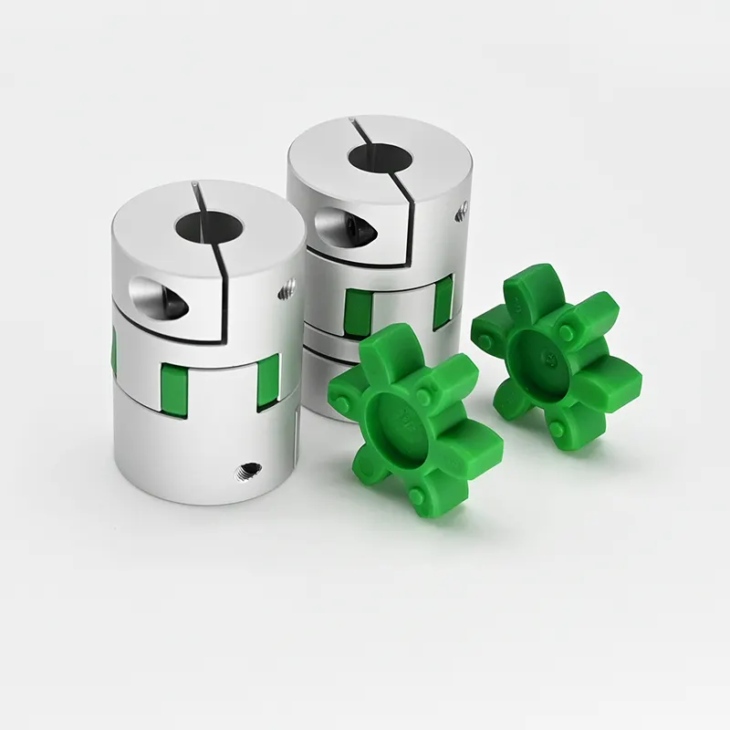
The ability of a jaw coupling to handle axial movement depends on the specific design of the coupling and the type of elastomer spider used. The elastomer spider serves as the flexible element between the two coupling hubs and is responsible for transmitting torque and compensating for misalignment. Some jaw couplings have an elastomer spider with axial flexibility, allowing the coupling to accommodate minor axial movements while maintaining effective torque transmission.
However, it is essential to note that jaw couplings have limitations regarding axial movement. They are not designed for significant axial loads or axial displacements. Excessive axial movement can lead to premature wear and damage to the elastomer spider, reducing the coupling’s performance and lifespan.
If an application requires significant axial movement compensation, other types of couplings may be more suitable. For instance, flexible beam couplings or bellows couplings are designed specifically to handle axial movement and are often used in applications where axial misalignment is a critical consideration.
In summary, while jaw couplings can handle a certain amount of axial movement, they are primarily intended for angular and parallel misalignment compensation. For applications with significant axial movement requirements, it is essential to consider coupling types explicitly designed for this purpose.
How Does a Jaw Coupling Protect Connected Equipment from Shock Loads and Vibrations?
Jaw couplings are designed to provide some level of flexibility, which allows them to absorb shock loads and dampen vibrations in mechanical systems. The unique design of jaw couplings contributes to their ability to protect connected equipment in the following ways:
- Spider Element: The spider element, typically made of elastomeric material, serves as a mechanical fuse in the jaw coupling. When the system experiences shock loads or vibrations beyond the coupling’s rated capacity, the spider element can deform or fail in a controlled manner, protecting the connected components from damage.
- Torsional Wind-Up: In the presence of torsional vibrations or sudden torque fluctuations, the elastomeric spider can act as a torsional buffer, absorbing and dissipating the energy to prevent it from reaching the connected equipment.
- Misalignment Compensation: Jaw couplings can tolerate a degree of angular, parallel, and axial misalignment between the shafts. This capability helps minimize stress on the connected components in situations where misalignments might occur due to external forces or dynamic operating conditions.
- Reduction of Resonance Effects: The flexibility of jaw couplings can help mitigate resonance effects that may arise in the system, reducing the risk of resonance-related failures or damages.
It’s important to note that while jaw couplings offer protection against certain shock loads and vibrations, they have their limits. Excessive or repetitive shocks, vibrations, or overloading beyond the coupling’s rated capacity can still lead to premature wear or failure. Therefore, it is essential to select the appropriate size and type of jaw coupling for the application and regularly inspect the coupling for signs of wear or damage. Regular maintenance and inspection help ensure the jaw coupling continues to provide reliable protection to the connected equipment.


editor by CX 2024-05-08